It is designed behavior as a part of flange enhancements in nx12.
Edit gap on sheet metal flange.
Could anyone help please im using inventor 2008 pro in the sheet metal format and having a slight problem with corners.
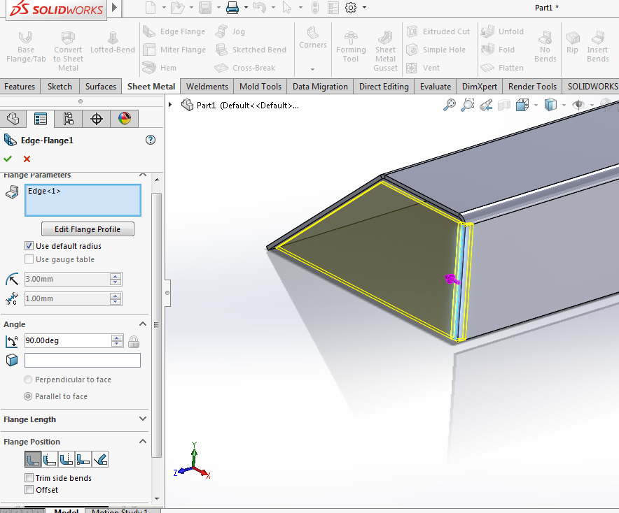
Edge flange see figure 3 can be used to add an attached wall to any sheet metal body.
Ive been trying to achieve this by creating.
You can override the default sheet metal.
There is note of it in the help documentation as to better support multiple instances within a feature the embedded sketch functionality has been removed.
Edit the sketch of the profile.
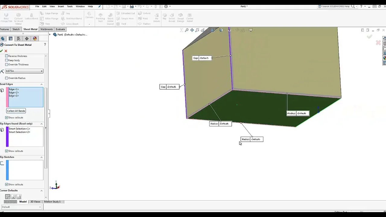
This same tool can be used to make a flat piece of sheet metal that one would use to add edge flanges and other useful sheet metal features.
The guys in the workshop are telling me that when they bend up an enclosure the edges of the flanges are always corner to corner.
Use gauge table only available if a sheet metal gauge table has been selected for the part select or clear.
Set a value when use default radius and use gauge table are cleared.
Next month concludes with the pros and cons of hems jogs and forming tools.
A flange feature consists of a face and bend connected to an existing face along a straight edge.
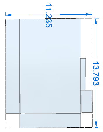
Previous editions covered economic order quantity in batch production and the accuracy of things made from rolled sheet stock.
To create a sheet metal feature click the sheet metal tab on the command manager and choose base flange enter a value of 1 50mm for thickness in the base flange options dialog box.
Columnist gerald davis continues a discussion of 3 d cad and precision sheet metal manufacturing in part iii of a four part series focusing on design guidelines for sheet metal.
You can use unbend rebend normal cutout bend taper and so on to customize flange shapes.
Options in basic sheet metal base flange tab.
Introduction to sheet metal features base flange method magazine file introduction to sheet metal features design communication graphics 5 sheet metal feature.
Cannot edit the corner gap in a sheet metal flange part file.